Tuesday, April 25, 2017

NO DRIPS, NO RUNS, NO ERRORS or CHAIRS, BLOCKS & LADDERS

Hey it's another season of baseball... thought the "title" would fit, and may be the Indians will win the World Series this year.

First, A WARNING!!!!! DON"T BUY DuPont Chroma System Paints  or new company Axalta paint!!!!!!! Long story short, if you breath on it IT CHIPS!!!!!!!!!

Long story, I have used PPG paints my entire life for car painting. Never had a problem other than what I did wrong. as I learned to paint a car. The usual runs, drips, sags, orange peel and over spray. In this case the PPG paints I would have used and SHOULD have used would have cost about $3,500.! I should have bit the bullet and paid the price. Being new to the area, I found out later that the local dealer was adding a very large premium to his prices. I should have looked and shopped around. A dealer 20 miles away would have been cheaper. The only other local paint dealer being a DuPont dealer had the paints  for $1,750.00. I went cheap after his assurances that the paint was every bit as good as the PPG. In mixing, blending and spraying, etc. it worked like the PPG paints. It was only during reassembly that it became apparent that the paint has NO DURABILITY, CHIP RESISTANCE or even bump resistance. Wherever the trunk, doors, trim and etc. touched, bumped or were drawn up by bolts there are chips. I taped all edges, joints, seams etc during fitting and reassembly. When I removed the tape there were chips! As the car sits now, it nearly needs repainted and has not even been on the road!!!!!!!!!!! The only thing I can say good about the paint is that the color is fantastic. But that is probably due to my color choice; Dodge Viper Brilliant Blue Pearl and Cadillac Diamond White Pearl.

ENOUGH of my rant!

I can't even begin to teach you how to paint a car.  So.... It took me all summer to prepare the body for painting. I did just like the TV shows: filling, smoothing, straightening sanding, priming and SWEATING: ALOT, to the tune that I lost better than twenty (20) pounds! Not that it hurt me! I did learn one thing. This car has large body panels without stamped body lines or accent lines. All it has is a slight curve or radius. No matter how hard (or soft) I tried, the panels would flex slightly, so could never sand to get a flat, straight surface regardless of how much filler was applied or sanded. I basically gave up.

How do I paint everything in a home garage, and to boot, do it in two (2) tone?

What we discovered during the disassembly was that some of the small sections of the car had "layers" of sheet metal that were held in place by clips, screws and body trim. That was how the factory did the two tone paint schemes. The small pieces were painted the alternate color and assembled in place. I can only guess how the factory did the large sections, but here's how I did it.

I had to cover and mask the car body below the roof line then paint the roof three (3) times. Base coat, pearl coat and clear coat. I had never painted a roof before and the car stands roughly five (5) feet tall. How the heck do I reach up that high without dragging my arm, spray gun, and the air hose on the roof or not touch the roof? I don't! I used several step ladders, 2" x 10"s and laid a "platform" around the perimeter of the body and "walked the plank." It worked reasonably well. Just be careful of the footing, openings and especially hose position. Sorry no pics of that.

Then how do I two tone the main body? Tons of tape, newspaper, old tarps and plastic drop clothes.  I followed the body trim line holes for masking. I figured the body trim pieces would basically split the line of the holes so I half masked them and had nice straight lines to follow. Apply the paint, base, pearl and clear coat. Let thoroughly dry, remove masking, and re-mask everything in reverse, for the other color.


 Prepped for white pearl. The top is done and covered.

Body prepped for white.


Body sections in blue.


The body in blue partially done. Quarter panels are in primer at this point.


Okay, that took care of the body, now what about the hood, fenders, inner fenders, trunk lid, doors nose piece and the other bits and pieces? Not having a spray booth and all the attendant holders, carts etc. What to do? One articulating ladder for door holder, some hand made hangers over the rungs, two (2) large tables for doors and parts, peg board garage wall with tarp for the hood, patio lawn chairs with concrete blocks to balance and raise fenders and overhead garage door tracks with heavy wire bent to support inner fenders and other pieces.

 The hood hung on the wall. It is said that pearls and metallic paints come out better if painted vertically. Less likely to tiger strip if you see it better.
 Doors on tables for back side and edge painting.
Radiator and fender inner supports.
Inner fender/ wheels, doors on tables in background.
 Fenders prepped for blue, white area masked out,
Back side of fenders. Note the patio chairs, masked and on concrete blocks. Back side of fenders are masked. There are also blocks on the chair seat to balance the weight of the fender.

 Fender in blue.

 Fender re-masked for the white arrow.

Doors "hung" on the ladder.

 Door done in blue with stripe still  masked over.
 Door re-masked for white stripe.
 Door is complete. Note the trim holes that were used to "draw" the paint lines.

 Body rolled out of the "paint booth." Arial view.
 Side view of the body.


Wednesday, April 19, 2017

JACKED UP!


After the body was sandblasted, epoxy primed and truck bed liner were sprayed I tackled the frame as previously described in FRAMED.  It may seem like a simple operation to switch the old frame with the modified one but it wasn't.

I had to figure out how to lift the body off the frame, roll out the old chassis, roll the "new chassis" in, and then lower the body back down and hit the body mount holes and studs. I could not use my rotisserie as I had made no provisions to make a body only connection to the rotisserie. Remember the pictures? I used the frame for all the lifting.

After more looking and measuring I decided to make some 4" X 4 ''s with 2"x 4" I had laying around. I planned on laying them on concrete blocks crosswise under the body. The "stacks" had to be outside the width of the body to clear the tires. It very quickly became obvious that would not work as the 4" x 4" lift points would crush the fenders and rockers.

I had to make some small 4"x 4" blocks and lay them on the crosswise 4" x 4"s and against the flat side of the body panels so they were in contact with the flat floor and as close as possible to reinforcing mounts or body mount connections.. Then, I had to make one short 4"x 4" to lay crosswise on the floor jack and fit between the frame rails and span the transmission tunnel gap. As usual, it was lift the front, then back, lay in concrete block and the 4" x 4"s back to front back and forth!

 As can be seen in the pictures I used 16 concrete blocks, four to each stack. It looked like everything was going well until my first attempt at rolling the chassis out! The trunk has a large well in the floor for the spare tire to sit in, in a near vertical position. The right rear wheel hit the spare well and obviously when the front wheel got there it would too!! More lifting and jacking! By now I was out of suitable 4"x 4" blocks so I scrounged our kindling piles and found 2" x 4"s and stacked 4 pieces at each point. A little wobbly.... but they worked. Out came the old chassis and in went the new!

Then work everything in reverse... lifting and jacking.  Before lowering the body I put new rubber body mount/ isolation "donuts" on the frame mounts. Surprise surprise! I got the "new chassis" within a fraction of an inch and was able align everything up with a little levering.

All jacked up!

INCOMING!!!!


Monday, April 3, 2017

SCARED TOWING!


Coming off the rotisserie we were finally ready to have the body sand blasted. We rolled the car out, still on the old frame, and hooked it up. Not sure how it would tow and track so we towed the car around the neighborhood. Everything went okay. So off we went to the sandblasters, about ten miles away.
Everything went well.

Two (2) days later it was ready to come home, so off we went again. The weather reports for the day were threatening rain late in the afternoon. My son and I got within a couple of miles from home and everything kind of went south!

We came up to a traffic light and made a right turn and the tow bar snapped and bent at a right angle!! BAD NEWS! Fortunately, I guess, there was a business drive with a lot of room, an unpaved drive and grass just ahead. I pulled over and parked. I ran inside and got got permission to "disconnect" and leave the car while we raced home to bend and weld the tow bar back into shape.

Once home there was no torch so we had to beat the bent section back into shape and use the sheet metal welding wire to effect a repair. It was the only wire I had left! I laid a number of welds one over the other. It look like CRAP! What else could I do? 

Off we went back to hook up and retrieve the car. We got all hooked  up proceeded very slowly. For the first mile it was a straight line with one stop sign. We were crawling with the four way flashers on. Traffic was light. Then we got to the main road, a three lane medium to heavy traffic road and a right turn required to continue! Yeah, it did it again! SNAP!!!

There are business along there, so again we maneuvered in. I knew we could not fix the draw bar with the weather threatening, so I convinced my son to sit in the open body and steer the car to follow the truck. I showed him and had him try the steering to understand it would take some real effort to turn it. I assured him we would be safe going slow and if the bar failed the worst that could happen would be the car slowly bumping into the back of the truck! 

He had to sit on the floor, peering out over the windshield frame and muscling the steering wheel to keep the car in line with the truck!!! I drove with one eye on the rear view mirrors and the other on the road, headlights and flashers on! Roughly half a mile up the road was a traffic light with a left turn lane with an incline, a less busy two lane road and mile from our house. The car tracked reasonably straight to the left and he was able to complete the turn. We managed to get the car home with a final left turn onto our street then a straight line to our house. My son was scared, but he did it!

As we were unhooking the car and preparing to roll it into the garage it started to sprinkle. We grabbed a camera and shot a picture or two and shoved it in .

Later we did an inspection, cleaning and vacuuming the sand and found one (1) small hole in the body that opened during the sand blasting. I spent several days cleaning and epoxy priming the body. As well as repairing and patching the hole, Later, I sprayed the under side, passenger compartment floor and trunk with truck bed liner. Had to buy a special gun and outside air temps effected the spraying. Instructions, in fine print, three pages in said 70 degrees or less!!!   Got the idea from a TV show. Later still, I the did the front inner wheel well liners and interior of the front fenders.

It never did rain that afternoon or evening.

Prepping to leave for the sandblast shop everything all hooked up.
                                                                                                                                              

Different angle of the car and tow bar.                                                                                                                                                                                                                                                                                                                                                                                                                                                                                                                                                                                                                                                                                                                                                                                                                                                                                                                                                                                                                                                                                                

We made it! The car as it came home from the
sandblasters.
                                                                                  
                                                                                  A different view of the car as it came home.                                                                                Look carefully at the draw bar.                 


The draw bar after after it was removed. We were done towing so it was cut up for scrap.


                                                                A close up of the failed weld.                        

Saturday, April 1, 2017

FLIPPIN" & FLOPPIN"


As I wrote earlier the assembled rotisserie's overall length when bolted to the chassis would leave the back of the rotisserie outside the garage wall. I had to add a 2 x 4 to the rear frame cross member to get the rotisserie lift to clear the trunk body flange..Once the car was in, and bolted to the lift arms, I nailed up an old boat tarp across the door opening to keep everything dry. 

I lifted the car using the floor jacks and winches moving from end to end to balance everything and keep the column lift sleeves from binding. They never did bind, but this was all new to me. The winches were strong enough to lift the car and hold it in position, but safety said use both. Once the body was in the air the main column was through bolted at both ends to assure it did not drop. I had made column base to column base floor connectors to keep everything aligned. I had not drilled them to secure them for proper length. That was a mistake. The columns kept trying to kick out at the base as I rotated the car. I had to use the 8 lb sledge hammer to keep them "adjusted" to proper length. As mentioned earlier, the vertical columns wanted to rock left and right; forward and back, due to the slip fit "slop" in the connector sleeves. The sleeve tolerance movement was about 1/16th inch but it compounded in height and width. I was always a little wary! 

As can be seen in the pictures, I did not quite get the lift arms bolted to the chassis for a clean rotation and full 90 degree rotation. Rather than play around I just worked as is. I also failed to get a proper height set up which limited the rotation with reference to the floor and the overhead garage doors. Again, it was positioned well enough to work, although it meant crawling and kneeling on the floor while repairing the inner wheel wells. 

The rotisserie allowed me to better access the underside floor for welding and grinding. It provided access to the back, flat side of the rocker panels and, with the rear wheels removed, full access to the inner wheel well flanges and skin. As the picture shows, I had to piece meal the curved arch of the inner wheel well skin. It also required very careful cutting with the cut off wheel to avoid cutting the outer fender skin. I also missed another hidden repair on the body mounts just in front of the rear wheel frame arch until the body was sand blasted, I am still a little puzzled by that one.

There is a hand machine tool set called a shrinker/stretcher which would have allowed me to do a one or two piece replacement but at the time they were VERY expensive. You can buy them now at HF very reasonably.                                                                                                                                                                                                                                Roughly one and half (1 1/2) tons up 3 feet.


Flipped better than 45 degrees.
                                                                                                                                                      
                                                                                Passenger side inner wheel well and flange with                                                                                       pieces welded into position. Note how close to the                             floor the body is.


Friday, March 31, 2017

FRAMED


In the five plus years it took to get to this point I had investigated what to do with front and rear brakes, a modern suspension and steering including power steering. During the course of the deconstruction of both cars we also found that the "good car" had been given a back yard repair. Cheap angle iron was welded top and bottom to the driver side frame rail just behind the rear wheel arch. 

At least part of the solution was sitting right in front of me. My Dodge Dakota pickup truck. No, I did not cut up my truck! I earlier mentioned many hotrod builders were using S-10 and Ranger truck frames and suspensions, as well as Mustang II front subs to upgrade their builds with more modern components and more readily available parts.

I crawled under my truck many times dreaming, measuring and figuring and just as many times measuring the DeSoto frame. As near as I could measure, a Dakota front sub would fit within a fraction of an inch.

I sort of half searched leaving my name and needs at a number of junkyards. After the body became viable I found a 2000 Dodge Dakota frame suitable for our project. The yard cut the frame extra long at my direction and I hauled it home. The sub-frame included the frame, front suspension and power steering rack and pinion. It did not include the disc brake components. All Dodge Dakotas used a six (6) bolt wheel pattern. It just happened that I had spiked snow tires and wheels for my truck.

Somewhere along the line and researching, I also found a few interesting facts about the Viper and Dodge Dakota relationship. It seems that Chrysler used parts from from existing car and truck lines to build the early Vipers. Depending on the source, some suspension, brake, spindle and wheel parts were used from the Dodge Dakota Truck line.

Knowing my welding skills and my 130 volt welder capabilities on heavy metal, I decided it would be best to seek outside help for the modifications. I found a local shop with many years of racing chassis repair and fabrication who was willing to under take the work. I gave him my sketches and dimensions and towed the frame from the parts car to his shop along with the "sub". I used a homemade tow-bar set up to bolt up to the bumper bracket frame horns.

The shop let me watch, but no pictures. First, he created a level support frame shaped like a capital "I". The top and bottom wings of the "I" caught the frame and acted as a table. "Devil's Horns" were added at the top of the "I" catching the DeSoto frame horns. We dropped the rear end so there be no imbalance when the front was cut. Then we measured everything making sure the wheel base would be correct. After layout, we decided that the Dakota section would best match up the DeSoto frame just about at the fire wall. Both frames were cut to length and positioned on the table

This location forced the removal of the transmission and frame support cross member. The cuts were made and the sections ground, joined, clamped, butted together and TIG welded. The inside frame rail weld was ground flat. For additional strength, a diamond shaped plate was heated, hammered to shape and overlaid (fish-plated) on the inside frame rail over the weld and TIG welded in. With the removal of the structural cross member we decided to add an X member of smaller heavy square steel tube with a drive shaft loop to maintain frame strength. A modified S piece was also added on the underside of the frame rails following the DeSoto/Dakota frame curve for reinforcement.

The radiator core support was removed from the DeSoto frame and welded into position on the Dakota frame. Lastly, the Dakota frame "horns" where the bumper brackets would attach were "Z" cut to avoid structure and provide strength and the corresponding DeSoto "horns" were cut to match and welded into place  

 Seen leaning against the garage wall is the homemade draw bar I used to tow the car frame to and from the shop. The modified frame is lifted for initial cleaning and temporary rust proofing, The frame alterations were done the summer of '06. I am the person pointing out features of the rotisserie to my wife's brother-in-law.


What is left of the parts car and the frame. Note: I have not yet removed the A frames from firewall when this picture was taken.

 The driver side frame joint. We were all taken by surprise at how well the Dakota frame matched up to the DeSoto frame. Note the forward most body mount "ear."
 Looking carefully, you can see the diamond plate reinforcement on the joint. This was after primer was applied to the frame. Looking just to the left of the rotisserie leg two (2) large holes are visible. That is the radiator core support pad.
The shot also shows some of the Dakota suspension and steering rack.

Looking from underneath to the passenger side, suspension components, steering rack and etc. Center left, on top of the cross member, the underside of the radiator core support with one bolt hole visible.

This picture, taken at a later date, shows the body mounted on the modified and painted frame. Shown is the transmission support cross piece and the permanent X cross member and drive shaft loop.


Later on I towed the frame to the sandblasters using the draw bar. Everybody asks me why a silver frame. Remember what I said about painting the '88 Sable? I Por 15'd the frame after the sandblasting and had a quart of left over silver poly from the Sable.... silver frame!!

Thursday, March 30, 2017

CAN U PUT A PIG ON IT?


A couple of years into this restoration now, I saw something on one of the TV shows about a rotisserie for turning and manipulating car bodies. I wrote away for the brochures and pricing. They came, and of course, they were EXPENSIVE and a ton to ship! I kept looking at the pictures and over the winter investigated steel tubes and shapes. I decided I could build one, so I drew up a plan and bought the necessary steel.

Using my trusty hand grinder with cut off wheels, I cut up the pieces per the plan, laid them out pieced them together to be sure of fit and function. After I was sure of everything, I proceed to weld them together. I then assembled everything and drilled holes for safety stops, different locations for height adjustments and of course spots to attach the car to the lift. To rotate the unit/car I bought an extra heavy duty six (6) foot piece of pipe. I simply raised the car, stuck the pipe into the open end of the lift and levered it over, dropped a bolt through the hole to keep it from further rotating

As it turned out the first thing I noticed was that using my floor jacks to lift and lower would not work real well.  I made a jack extension using an axle and hub welded on to give me a total lift height of 55 inches.The hub sat neatly in jack saddle.

I had a large boat and trailer. To get it back on the trailer required a winch and heavy duty rated cable. My son, by now old enough to work after school, was working at a local outlet of a marine supply store. I had him get two (2) heavy duty winches, cable and pulleys. I added them to the design. They worked okay with the jacks and were more than able to support the entire car shell. It was just kind of a pain going from one end to other alternating lifting or lowering each end and keeping everything in balance and keep everything from binding.

The next thing I noticed was that the entire unit was very stable on soft soil in the yard while I was working on the frame. On the hard garage floor it wobbled a little due to the slip fit of the removable leg extensions. It was just slightly unnerving!

The next flaw in the design was that with all the attachments bolted to the car I could not close the back overhead garage door as the unit stuck outside the garage door/house frame. To keep the weather out I put a tarp across the door opening.

The last flaw was easily overcome. The design did not rise high enough to completely invert the car body. The best I could do was 90 degrees. Good enough for all that I needed to do. I later sold the unit to a young guy who like wise could not afford what was on the market at the time.

We live in an area with a lot of different ethnic peoples. Many of them struggle with the English language. When I sold the CAR ROTISSERIE on Craig's List I got several calls about the rotisserie and whether it could handle a pig or side of beef! It was a hoot trying to explain what I was selling!!!!!!!
A couple of pictures follow of the rotisserie showing key sections of it's construction while being used to manipulate the frame of  the parts car.


Tuesday, March 28, 2017

LOOKIN' UP


As I said earlier, as soon as we started disassembly, it became readily apparent  that I may have been taken. As soon as the front clips (fenders, hoods, inner wheels, etc.) came off it was VERY glaringly apparent that there was MAJOR rust damage to what is called the A post base on both sides of the "good car".   As nearly as I can describe it, the A post is the lowest most forward section of the body extending up to the roof. It is usually a boxed section where doors, rocker panels, floor, any body mounts, firewall, and windshield connect.  Due to it's complex connections, and location it was practically impossible to see the base and damage. The fenders wrapped down and around the "foot" or base of the column and the rocker panels extended forward partially hiding it too. It was very disheartening to see.

Trying to be positive, that's why we tackled the previously described repair and replacement work. All that work took several work "seasons" as told in Y ZZt TAKEN SO LONG? We were also salvaging the parts car, keeping what we might need and trying to keep the neighbors happy. Each time the season ended the car was rolled out of the garage and tarped for the winter. As fate would have it, the passenger side base of the A post sat right in front of the laundry area basement window. That meant every time I was near the sink, or helping with laundry, my eyes were drawn to and LOOKIN' UP with disgust at the damage.


I finally resolved that it was time to work on the A post situation. If I couldn't make the repairs the project was doomed. If I could, it was viable. I very carefully laid out the cuts on what remained of the parts car and salvaged the sections including the floors, frame braces, body braces and rocker panels. A picture of the remainder will appear under FRAMED. After removing them, and given the season, I decided to work on them all winter in the basement. It meant countless hours of careful disassembly, sketching and measuring of the part making up the base of the A post. And remember there two (2) sides, in mirror image ( reverse position and angles).

The base of the post had multiple layers or pieces of metal. Remember what I said about metal flanges, overlaps and moisture? I could identify the interior floor, floor of the A post, flange of the rocker panel, one body mount structural member and one piece that served some kind of structural purpose.

The original body mount has flats at both ends with  raised center somewhat like a small w about 2 inches wide with a 3/8 inch raised sides. It narrows from its base at the rocker to the frame mount. It acted like a trough holding and feeding water to the entire joint. I added a small drain hole on each side of the channel at its base.To duplicate the body mount structural member required me to make thirteen (13) separate pieces and edge and butt weld them together to get the necessary shape and fit. That was for each side! I was going in and outside all winter to cut and weld the little pieces. Of course I couldn't always go due to snow and cold etc.

Picture a large tube. Then cut it into quarters. That yields an odd shaped "D". Then notch the edges and bend a 1 inch flange. Add to that a back section  and you have  the unseen section of rocker panel. I made several paper and art board patterns to make a one piece "D " shaped tube. Since the rocker panel had no end cap . I added a slide in end cap with vent to reduce water intake into the rocker panel.

For the floor I cheated. I thought replacement floor sections for a chevy truck might fit so I ordered a pair from LMC. When they came, I test fitted them and they were about perfect. I put them upside down (bend up) gave them a light "stomp" and they were perfect! They do have grooves and steps which caused minor problems when it came time for carpet. I set them aside until the A posts were ready to be installed.

The left and right floor
pieces from LMC. Note
I have already punched
the holes for spot
welding.


Come spring and summer the hard part started. I had to very precisely lay out the cuts for "good car."
But before that, I had to reinforce the body of the car to made sure that it did not bend or collapse when the A post was removed. We had a damaged heavy duty bed frame made of 1 1/2" angle iron. I measured for length, welded on feet or ends, drilled them for bolts and bolted them to the door hinge locations and door latch bolt holes. I added a swivel leg with foot extending to the floor. That gave me angled and vertical body support. Then the old rule, with extra caution, Measure 3 times cut once!!!!!!!!!!


With  me in the background working on the bracing. The passenger side brace is visible in the fore ground with the vertical brace not yet deployed.


The passenger side floor rot and the masking tape layout for the cut.


                                                                                 The passenger side A post and floor removed.


The underside of the passenger side A frame shows the rot of the brackets, rocker and floor.

The passenger side A post from the parts car rebuilt. Note the rocker and the water shield I created. The body mount underside is unpainted and shows the complex shape. The floor is not installed as it had to be spot welded in two (2) planes.


From inside the car, passenger side after the floor plate was welded from inside and from the under side to the A frame.


The passenger side fully welded in and welds ground out. I intentionally left a little weld showing to show the "scars" of the repair.
Clearly visible is the vertical and horizontal body
supports and how they meet the frame "ear".
The driver side floor and A frame removed. The hole appears overly large as there is a plate removed which accommodated the steering column pass through.

The driver side A frame removed. Note the large missing section of floor and exposed structural supports. The hole further up the floor section was for the headlight dimmer switch.


The under side of the repaired driver side A frame. Note the visible "layers" of the structure: floor, brace and structural cross member.


The driver side A frame laying on it's side showing the rocker, support and structural cross member.


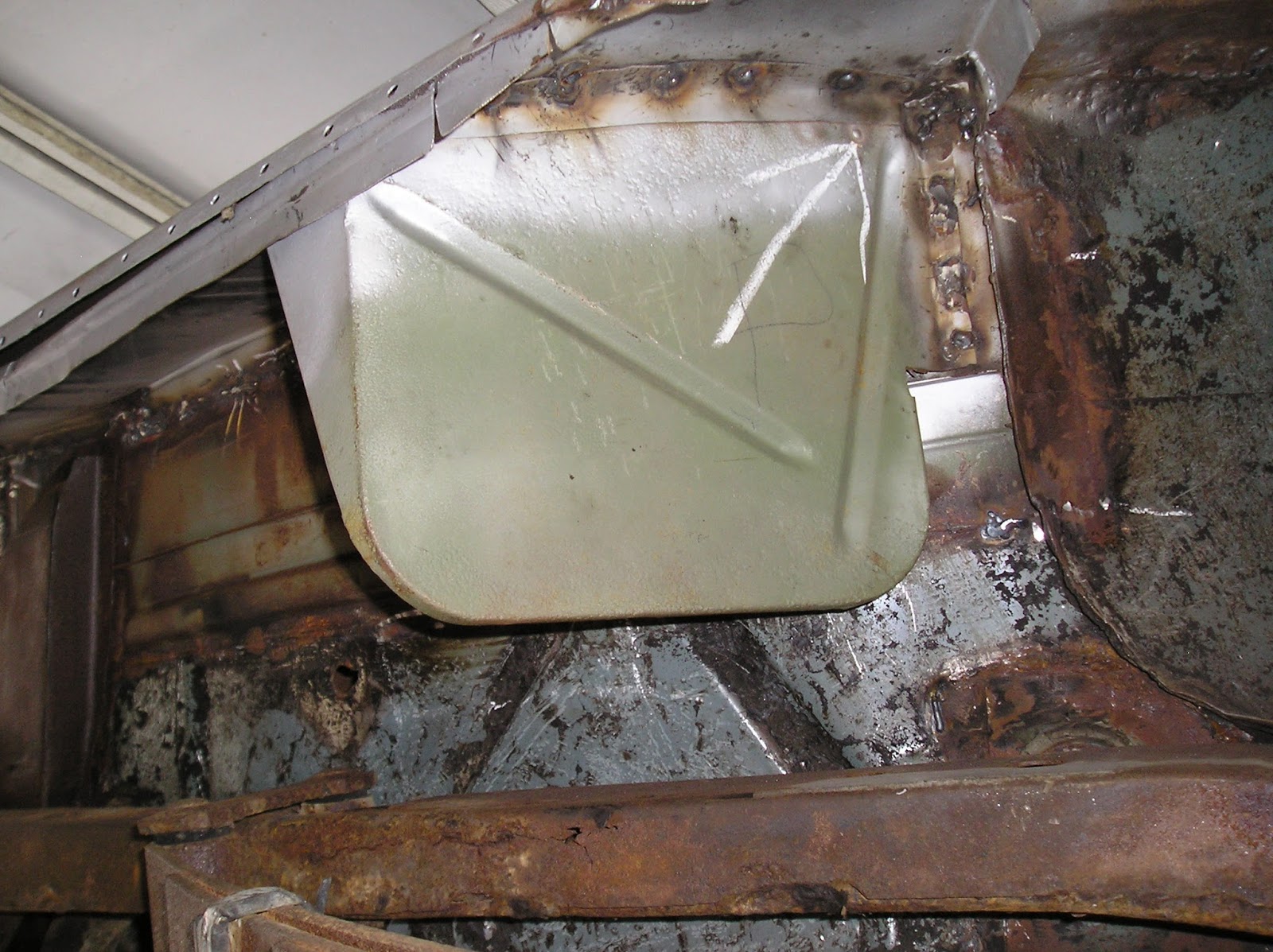
When the A frames were cut out it exposed more lies about the repairs of the rocker panels. The first picture of this page shows a little of the backside of the rocker. It is loose at the top. The back side of the panels were laid in loose and tarred in place. None of the structural floor supports were welded in to the vertical back side of the rockers. I had to fabricate new back sides for the rocker panels and top of the sill plate, then slit the top of the rockers open across the door sills, remove part of the door sills and drop in modified T's. The top of the T was offset so that the vertical backside replacement met the lower flange on the rocker panel and the structural floor supports.
I had to spot weld the rocker panel flange and the T and the structural supports in place. While I was at it, I added an angled drain hole in he rockers as they are known to rust due to lack of drainage. Then I had to continuous weld the top sill of the rocker.
Further compounding the situation, my sheet metal bender is to short to accommodate the length of the pieces required so I had to butt weld them into a single unit. You can see the welded seams.
One complete T is seen along with the pieces necessary for the other.

At the end of the summer I knew we had a shot at a viable car for a complete restoration!